
|
Truth Tables and Logic |
A mathematician called Bool invented a branch of maths for processing true and false values instead of numbers. This is called Boolean Algebra. Simple Boolean algebra is consistent with common sense but if you need to process decisions involving many values that might be true or false according to complex rules, you need this branch of mathematics.
| Rule | One Line Explanation |
AND |
1 AND 1 gives 1. Any other input gives 0. |
NAND |
(NOT AND) 1 AND 1 gives 0. Any other input gives 1. |
OR |
0 OR 0 gives 0. Any other input gives 1. |
NOR |
(NOT OR) 0 OR 0 gives 1. Any other input gives 0. |
XOR |
Equal inputs give 0. Non equal inputs give 1. |
NOT |
Invert input bits. 0 becomes 1. 1 becomes 0. |
Computers work using LOGIC. Displaying graphics such as the mouse cursor involves the XOR (Exclusive OR) command. Addition makes use of AND and XOR. These and a few of the other uses of logic are described below.
The one line descriptions of the rules above are clearer if shown in Truth Tables. These tables show the output for all possible input conditions.
Logic gates are the building blocks of microcomputers. Modern processors contain millions of gates. Each gate is built from a few transistors. The gates are used to store data, perform arithmetic and manipulate bits using the rules above. The XOR rule can be used to test bits for equality.
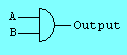
Both inputs must be true for the output to be true. AND is used for addition and decision making.
 -----------
  A B Output
 -----------
  0 0    0
  0 1    0
  1 0    0
  1 1    1
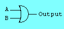
Both inputs must be false for the output to be false. OR is used in decision making. Both AND and OR are used for Bit Masking. Bit masking is used to pick individual bits out of a byte or to set particular bits in a byte. OR is used to set bits to one. AND is used to set bits to nought. AND is used to test if bits are one. OR is used to test if bits are nought.
 -----------
  A B Output
 -----------
  0 0    0
  0 1    1
  1 0    1
  1 1    1
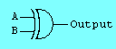
If the bits in a graphical image are XORed with other bits a new image appears. If the XORing is repeated the image disappears again. This is how the mouse and text cursors get moved around the screen. XOR is combined with AND for use in addition. XOR detects if the inputs are equal or not.
 -----------
  A B Output
 -----------
  0 0    0
  0 1    1
  1 0    1
  1 1    0

NAND is really AND followed by NOT. Electronic circuits are commonly built from NAND gates (circuits). Computer programming languages and this simulator do not provide NAND. Use NOT AND instead.
 -----------
  A B Output
 -----------
  0 0    1
  0 1    1
  1 0    1
  1 1    0
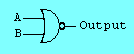
NOR is really OR followed by NOT. Electronic circuits are commonly built from NOR gates (circuits). Computer programming languages and this simulator do not provide NOR. Use NOT OR instead.
 -----------
  A B Output
 -----------
  0 0    1
  0 1    0
  1 0    0
  1 1    0
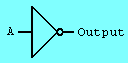
NOT is used to invert bits or True/False values. All the rules above had two inputs and one output. NOT has a single input and output.
 -----------
  A  Output
 -----------
  0     1
  1     0
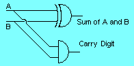
The half adder does binary addition on two bits.
The AND gate conputes the carry bit.
The XOR gate computes the sum bit.
0 + 0 = 0, carry 0
0 + 1 = 1, carry 0
1 + 0 = 1, carry 0
1 + 1 = 0, carry 1
 ------------------
  A B   SUM  CARRY
 ------------------
  0 0    0     0
  0 1    1     0
  1 0    1     0
  1 1    0     1
© C Neil Bauers 2003